TM 11-6625-847-45
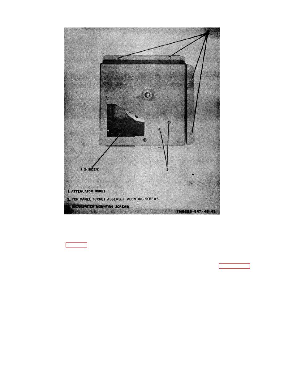
1 Attenuator wires
2 Top panel turret assembly mounting screws
3 Microswitch mounting screws
Figure 3-8. Driver, discriminator, and antenna coupler tray A1A5, turret assembly, top view.
3-20. Disassembly of Mixer Assembly
b. Loosen the setscrew securing the two-tone
To disassemble the mixer assembly after removal from
LEVEL control knob (fig. 3-12) on the front panel;
the test set, remove the two screws and four washers,
remove the knob from the panel.
then remove the cover.
Note.
To remove electrical components, use
subassembly A1A5.
conventional techniques Refer to paragraph 3-1.
d. Remove the two front panel screws which
secure the mixer assembly to the front panel. Remove
3-21. Reassembly of Mixer Assembly
the mixer assembly from the test set.
To reassemble the mixer assembly, proceed as follows:
3-11


 Previous Page
