
TM 11-5840-360-14-1-1
5.12.2.13 Lamps
5. Reconnect the harness connector P101 to the
power supply assembly 4/5A1.
1. Remove power per paragraph 5.12.2.
6. Reconnect the Anode lead to the CRT and the
Focus lead to the power supply assembly 4/5A1.
2. Remove all lamps by turning the retaining
7. Mechanically isolate the power supply chassis
spring to the side.
from the Indicator cabinet by placing a clean folded-up
3. Remove all lamps by pulling them out of their
cloth between them.
socket holders.
8. Electrically ground the power supply chassis to
4. Reinstall using the reverse of above.
the indicator cabinet with a clip lead.
9. Verify that all PCBs (including the extender
5.12.3 Alignment Procedures
card) are inserted in their proper locations in the A2
Card Basket.
provide instructions for alignment of all shipboard
10. Set the Indicator POWER switch to TX ON.
adjustable maintenance controls contained in Azimuth
11. Connect an oscilloscope to the collector of
Range Indicators IP-1282 and IP-1283.
When
A1A2Q103.
performed in the sequence indicated, these instructions
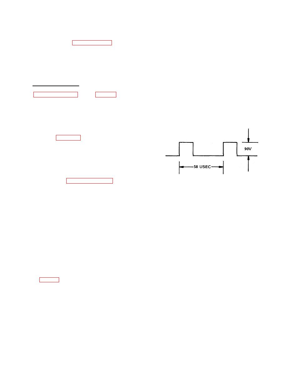
12. Adjust the FREQ-SET control A1A1R47 to
constitute an overall Indicator alignment procedure. The
obtain the waveform shown below:
alignments should be checked and adjusted as
necessary following all Indicator repair and replacement
activities. Refer to Figure 5-7 for location of assemblies
and major components.
5.12.3.1 Power Supply Adjustments, - This procedure
provides instructions for adjustments of power supply
operating frequency, output voltage level, CRT coarse
brilliance and CRT focus. Adjustment of the power
supply overvoltage/overcurrent (OVP/OCP) protection
circuit is covered in paragraph 5.12.3.2 following.
13. Connect a multimeter, set at 10 Vdc scale,
Perform the following steps in the sequence given.
between pin 5 (positive lead) of the extender card and
chassis.
NOTE:
14. Adjust OUTP ADJ control A1A1R28 for a
Power Supply A1 contains two
reading of +5.1 Vdc on multimeter.
controls which are factory set and
15. Disconnect multimeter.
Set SERVICE/
should not be adjusted in the field;
OPERATE switch A1A2S101 to OPERATE.
these are:
WARNING
a. High voltage control A1A3R205.
HIGH VOLTAGE IS PRESENT.
b. PULSE WIDTH ADJ control A1A1R33.
16. Turn front panel BRILLIANCE control fully
1. Set the Indicator POWER switch to OFF.
clockwise.
Adjust BRILLIANCE PRESET control
2. Remove the access cover from the front of the
(A1A2R112) until sweep is barely visible on CRT
Indicator.
display. Adjust front panel BRILLIANCE control for
3. Carefully disengage the A1 High Voltage Power
desired sweep intensity. Adjust GAIN and CONTRAST
Supply from the Indicator cabinet by removing three
fully CCW.
screws per 5.12.2.1.
17. Adjust front panel RANGE RINGS control for
WARNING
desired range ring brightness. Adjust FOCUS control
SET
THE
SERVICE/OPERATE
(R111 on Potentiometer PCB A1A4) to obtain the
SWITCH A2S101 TO SERVICE TO
sharpest possible definition of the range rings on the
DISABLE THE HIGH VOLTAGE
CRT display.
OUTPUT OF THE POWER SUPPLY.
18. Set Indicator POWER switch to OFF.
19. Remove the grounding clip lead and the
4. Position the power supply for easy access to the
protective cloth, and carefully Install the A1 High
screwdriver adjustment potentiometers on the back and
Voltage Power Supply into the Indicator cabinet.
to transistors A12Q101 through Q104 on the side.
5-56


 Previous Page
