TM 11-5840-281-12-1
3-4. CURSOR ALINEMENT CHECKS. (CONT)
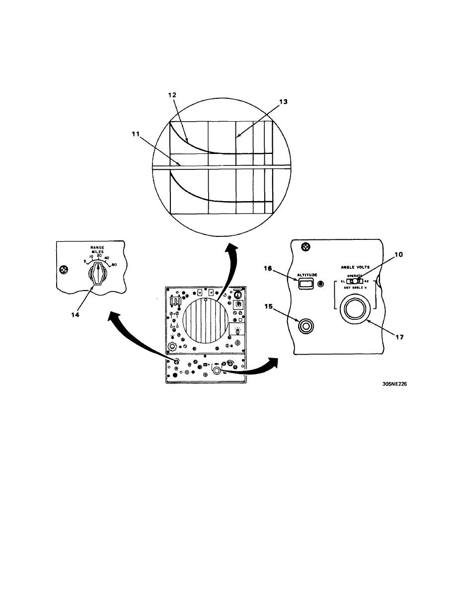
8. Accurately set ART ANGLE V control dial (9) on both control-indicators to 7-mile intercept setting recorded
during initial circuit alinement.
9. Momentarily place ANGLE VOLTS switch (10) to EL position and then back to OPERATE. (The artificial
sweep trace (11) will appear on the elevation display when the ANGLE VOLTS switch (10) is placed in EL
position.) Check that height finder cursor (12) intersects 2-mile range mark (13) where the artificial sweep
trace (11) crosses the 2-mile range mark (13).
10. Place RANGE MILES switch (14) on both control-indicators to 20 position.
11. Set ALTITUDE control (15) to indicate field elevation plus 15,000 feet in counter window (16) on both
control-indicators.
12. Accurately set ART ANGLE V control dial (17) on both control-indicators to 10-mile intercept setting
recorded in the circuit alinement procedures.
13. Momentarily place ANGLE VOLTS switch (10) on both control-indicators to EL position and then back to
OPERATE position; check that height finder cursor (12) intersects 10-mile range mark where artificial sweep
trace (11) crosses 10-mile range mark.
3-9


 Previous Page
