TM 11-5840-281-12-1
3-4. CURSOR ALINEMENT CHECKS. (CONT)
NOTE
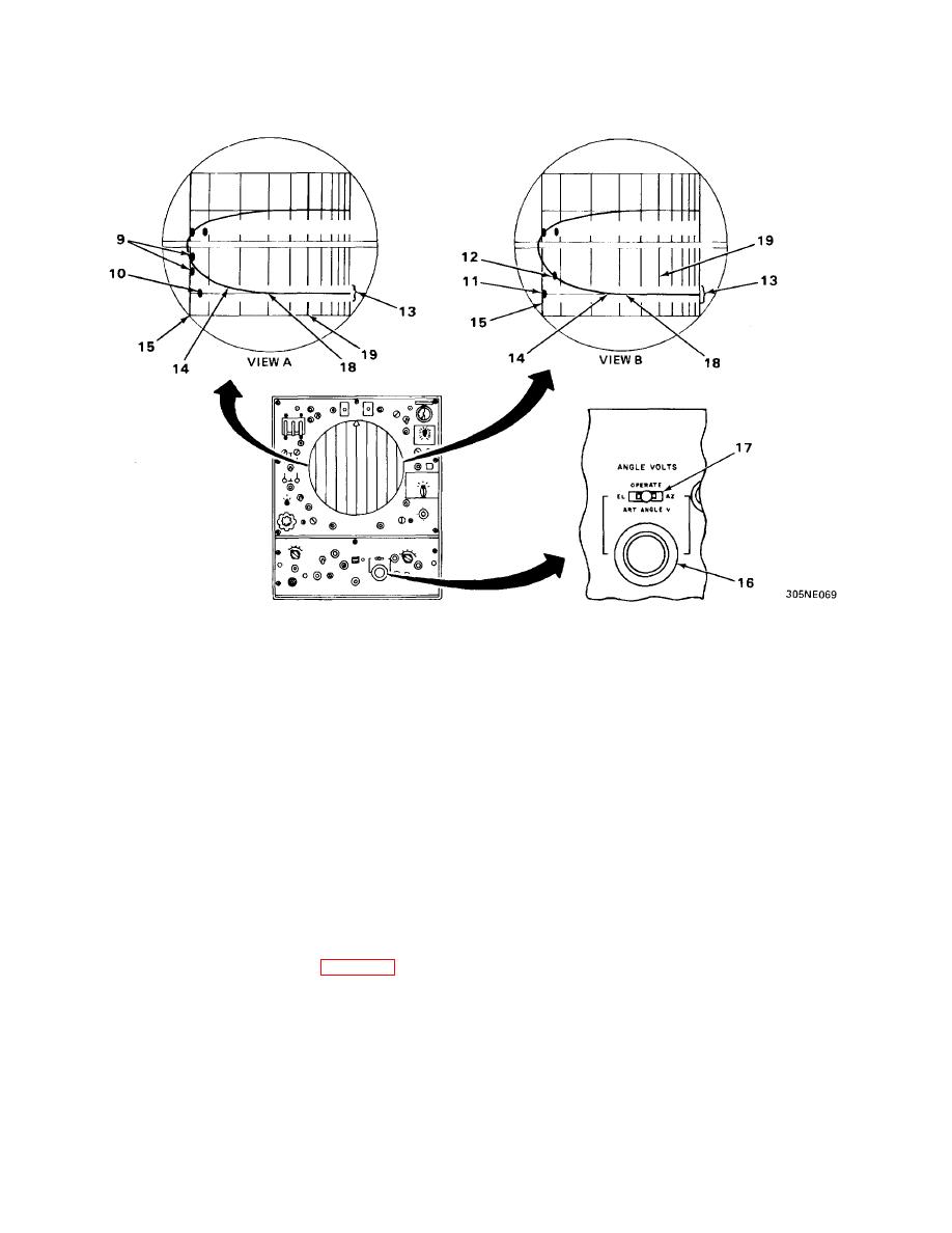
There are two views to represent the two configurations of target reflector
placements. View A illustrates two target reflectors (9) placed on either side of
runway and one target reflector (10) representing the runway parallel line. View
B illustrates one target reflector (11) representing the runway parallel line and
one target reflector (12) representing the centerline-of-runway. The blanked
section (13) in the range marks represents servo position of elevation antenna.
For right-of-runway coverage, the azimuth cursor (14) will curve down; for left-of-runway coverage the azimuth cursor will
curve up.
9. Check that touchdown range mark (15) passes through the leading edge of target reflectors, (9, view A), or (11, view
B) in the azimuth display on both control-indicators.
10. Check that the closed-in or curved portion of the azimuth cursor (14) bisects the distance between the target
reflectors (9, view A), or bisects the target reflector (12, view B) in the azimuth display on both control-indicators.
11. Accurately set ART ANGLE V control dial (16) on both control-indicators to the 5-mile intercept setting recorded
during the initial circuit alinement (para 4-28).
12. Momentarily place ANGLE VOLTS switch (17) on both control-indicators to AZ position, then back to operate
position. (The artificial sweep (18) will appear on the azimuth display when the ANGLE VOLTS switch (17) is in the
AZ position.) Check that the azimuth cursor (14) inter-sects the 5-mile range mark (19) where the artificial sweep
trace (18) crosses 5-mile range mark (19) (view A or B) in azimuth display on both control-indicators.
3-5


 Previous Page
