TM 11-5840-281-35/1
ity. The result is that a positive trigger is produced 5.0
itive trigger on the secondary winding. This positive
sec after the system pretrigger is applied to the delay
trigger is then fed to the grid of thyratron modulator
line.
V202, triggering V202 into conduction.
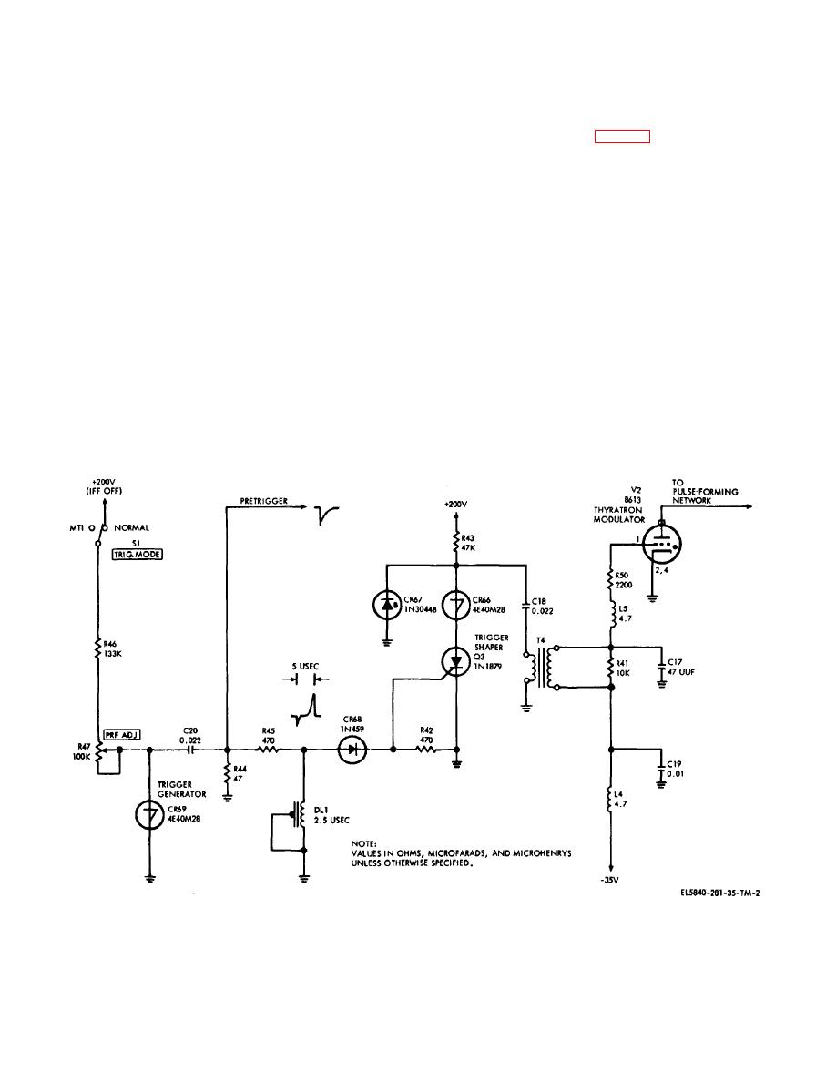
(3) The trigger shaper circuit consists of silicon-
c. Modulator Circuit (Fig. 2-3). The modulator
controlled rectifier Q203; four layer diodes CR266,
circuit consists of thyratron modulator V202, charging
CR267, and CR268; resistors R242 and R243; and
choke L201, hold-off diode E202, pulse-forming network
capacitor C218. The positive trigger from the delay line is
Z201, pulse transformer T202, and magnetron rf
applied through diode CR268 to silicon-controlled
oscillator V201.
rectifier Q203 and causes Q203 to conduct. During
(1) Pulse-forming network Z201 is part of a
conduction, silicon-controlled rectifier Q203 is essentially
series resonant charging circuit comprising charging
a short circuit, raising the potential across four layer
choke L201 and pulse-forming network Z201. During the
diode CR266. The potential across diode CR266
period between pulses, pulse-forming network Z201
exceeds its 40-volt breakdown voltage, and both diode
charges to a value determined by the reference-voltage
CR266 and silicon-controlled rectifier Q203 act as a
Zener network in the high-voltage regulator circuit. The
short circuit, which discharges capacitor C218. Upon
preselected values may be 8475, 8675, 8875, 9075, or
discharge of capacitor C218 the small current through
9275 volts, as determined by the power output
resistor R243 is below the holding value of diode CR266
requirement. The high-voltage charge developed across
(in series with silicon-controlled rectifier Q203) which
the components of the modulator circuit is the result of
then ceases to conduct and becomes an open circuit,
a resonant rise of voltage. The pulse-forming network
placing silicon-controlled rectifier Q203 in a quiescent
reaches its charge in approximately half the pulse
state until the next initiating trigger. The discharge of
repetition time. When the preselected high voltage
capacitor C218 through the primary winding of
reference has been reached, the magnetic field in
transformer T204 develops a high-amplitude, pos-
charging choke L201 is collapsed by the action of the
electronic
Figure 2-2. Trigger generator and shaper circuit, simplified schematic.
2-4


 Previous Page
