TM 11-5840-281-35/1
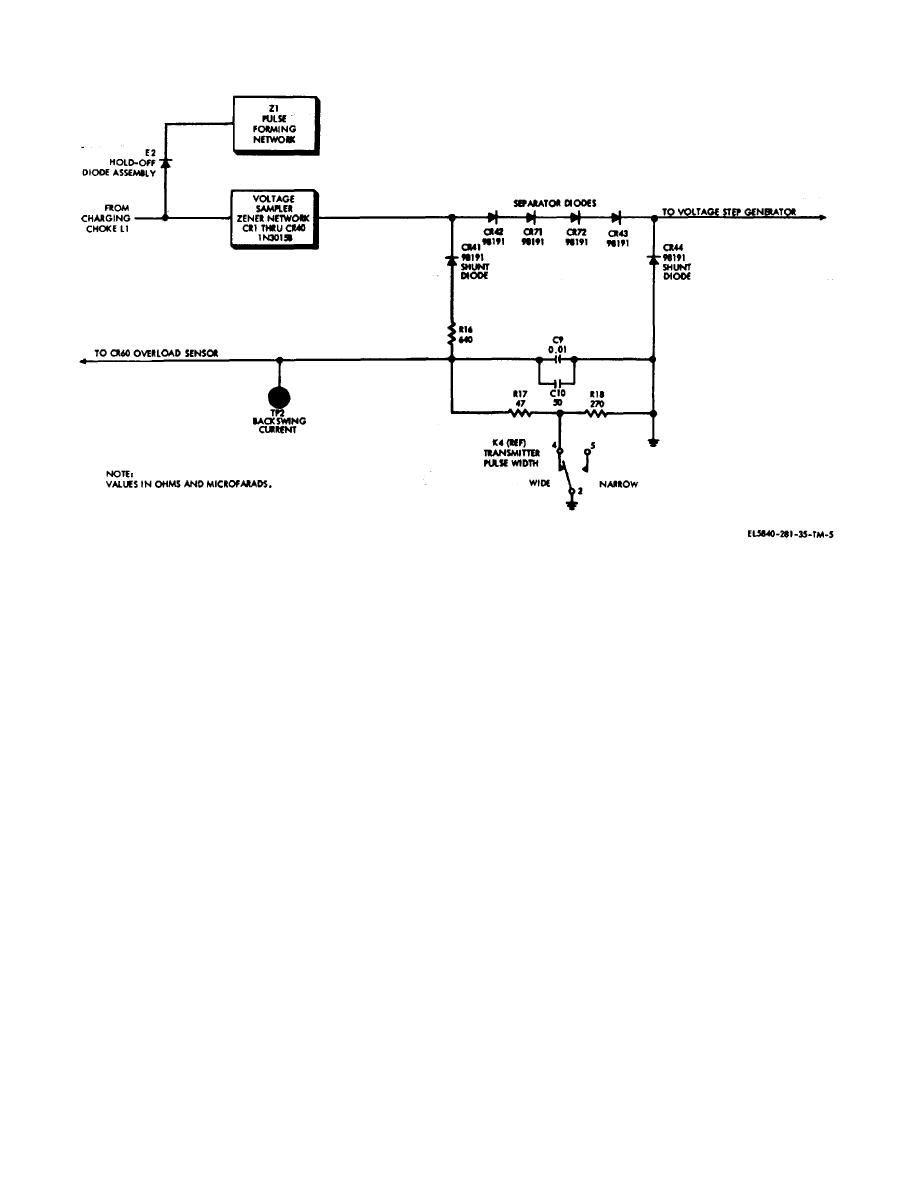
Figure 2-5. Backswing circuit, simplified schematic
This condition would produce a negative charge on the
(1) The common emitters of transistors .204
pulse-forming network and, if allowed to continue, the
and Q205 are returned to ground through
accumulative buildup of the negative charge would
TRANSMITTER switch S603 on Control-Indicator C-
ultimately break down the pulse-forming network. Zener
6988/TPN-18. With base current flowing through resistor
diode network CR201 through CR240 provides a
R238, transistor Q205 is switched on and completes the
reverse current discharge path through diode CR241,
return circuit of the solenoid winding of relay K201.
since any negative charge biases these diodes in a
Should the voltage at the anode of diode CR260, which
forward direction. Separator diodes CR242, CR271,
is proportional to backswing current, exceed -- volts,
CR2, and CR243, when reverse-biased as a result of the
diode CR260 will conduct, and the base of transistor
negative charge, keep the backswing current from
Q205 will be driven negative to cutoff.
flowing through the voltage step-generator circuit.
The contacts of relay K201 will open, disconnecting
Excessive backswing current flows through diode
primary power from high-voltage transformer T201.
CR241, and resistors R216 and R217 to ground. The
(2) Should the voltage across resistor R226 and
voltage developed across resistor R216 is applied to the
R227, which is proportional to rectifier current, exceed -
overload sensor circuit. The voltage developed across
11. volts, Zener diode CR269 will conduct and the base
resistor R217 (wide-pulse operation) is averaged by
of transistor 205 will be driven negative below cutoff,
capacitors C209 and C210. Resistor R218 is switched in
opening the contacts of relay K201. Resistor R249 and
series with resistor R217 for narrow-pulse operation,
Zener diode CR258 protect Zener diode CR259 from
since less average backswing current will be developed
current surges which occur when the high voltage is first
during narrow-pulse operation when the magnetron arcs.
turned on. Capacitor C223 filters the rectifier cur- rent
e.
Overload Sensor Circuit (Fig.2.6). The
pulses, and effectively converts the signal to a de
average.
overload sensor circuit principally consists of transistors
(3) Should the voltage across resistor R225,
Q204 and Q205.
2-7


 Previous Page
