TM 11-5840-281-35/1
switch which swamps the secondary. The conduction of
The high-voltage regulator circuit limits the resonant rise
silicon-controlled rectifier Q201 causes a. voltage drop at
of voltage across the pulse-forming network of the
the junction of charging choke. L201 and hold-off diode
modulator circuit by sampling the high voltage on the
E202 of approximately. 2000 volts. This sudden drop in
output of charging choke 1201, and by ending the charge
voltage reverse-biases hold-off diode E202, and
cycle when a preset voltage limit is reached.
essentially disconnects the pulse-forming network from
(1) The network of Zener diodes CR201 through
the charging source.
CR240 has a total breakdown voltage of approximately 8
kv. Four more Zener diodes (CR245 through CR248)
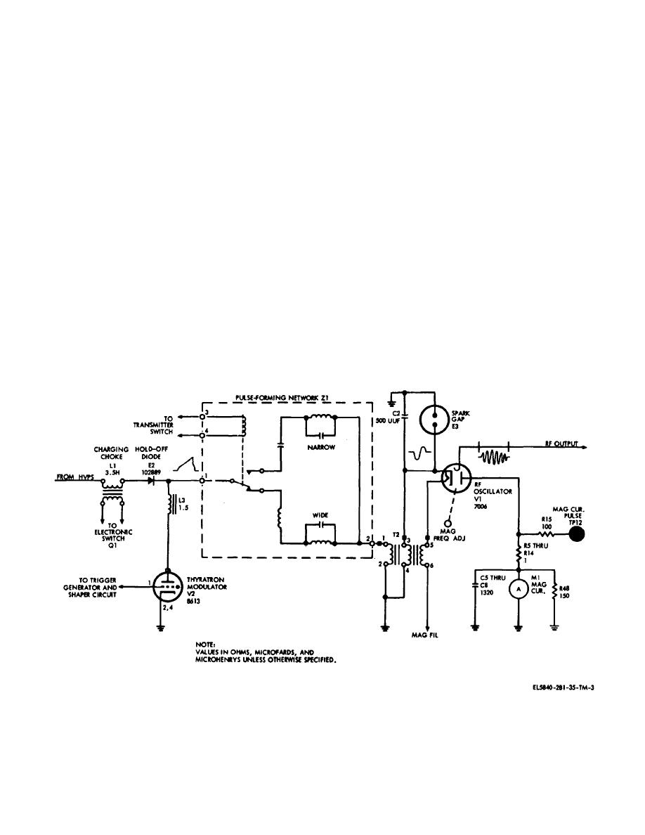
(2) When the thyratron is triggered, the pulse-
may be added at terminal board TB201 to change the
forming network discharges through the primary winding
voltage limit of reference level as required to set the
of pulse transformer T202. The high-voltage, negative
output power at 200 kw. Each added diode at terminal
pulse developed in the primary winding of pulse
board TB201 increases the high voltage by
transformer T202 is stepped up by a ratio of 1 to 6 in the
approximately 200 volts. As the charge on the pulse-
secondary bifilar windings. The pulse developed is either
forming network increases, the Zener network reaches
0.2 or 0.8 sec in duration, depending upon which 1c
its breakdown potential, increasing the voltage drop
across divider network R221, R222, and R223 to
circuit of the pulse-forming network is in the circuit. The
approximately 475 volts. When the 475 volt reference
high voltage negative pulse is applied to the cathode of
voltage is reached, Zener diodes CR249, CR250, and
magnetron rf oscillator V201, causing V201 t oscillate for
CR251 break down, developing the gate current for
the duration of the pulse. The magnetron frequency is
silicon-controlled rectifier Q202. Zener diode CR254
adjustable between 9000 and 9160 MHz. Rf energy
clamps the negative voltage at the junction of resistor
developed. by the magnetron is coupled to the rf section
R219 and diode CR254 near 0 volt. This limits the gate
and. to the antennas. Magnetron current is monitored by
current voltage developed for silicon-controlled rectifier
MAG CUR meter M201. Meter M201 is connected
Q202 to a value of 15 volts, by reverse current
between the magnetron anode and ground.
breakdown. The gate current developed for sili-.
d. High-Voltage Regulator Circuit (Fig.2-4).
Figure 2-3. Modulator circuit, simplified schematic.
2-5


 Previous Page
