TM 11-5840-281-35/1
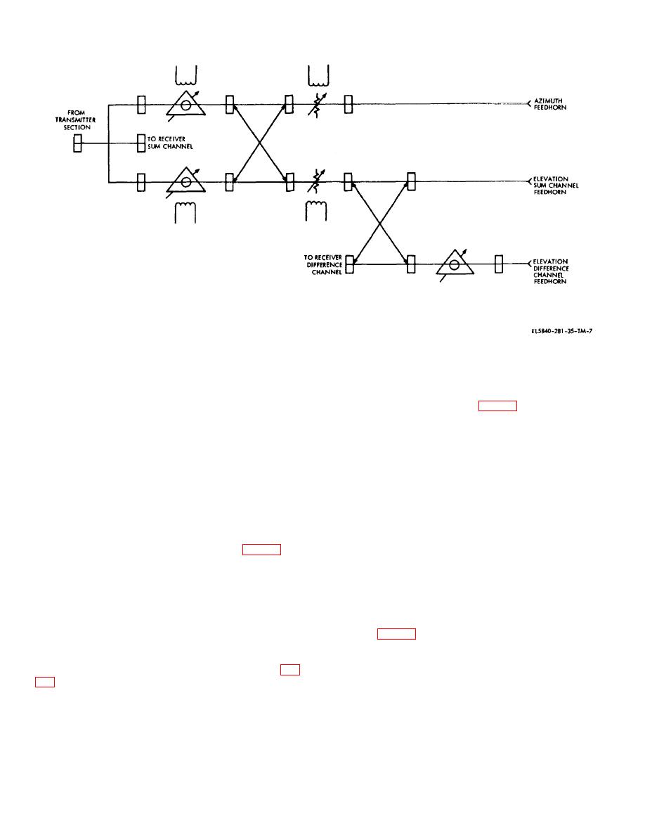
Figure 2-7. Rf section, simplified schematic
switch, an azimuth and elevation attenuator, a single-
line 1 of the ferrite waveguide section passes through the
channel azimuth feedhorn assembly with a linear/circular
short-slot coupler (with no phase shift) to the azimuth
polarizer assembly, a dual-channel elevation feedhorn
channel waveguide at point C (fig. 2-8). The other half of
assembly with a linear/circular polarizer assembly, two
the energy passes to the elevation channel waveguide
paraboloid antenna reflectors, and interconnecting
but is caused to lag 90 degrees by the short-slot coupler.
waveguides. Operation of the rf section is given in the
The energy from line 2 of the ferrite waveguide section is
description of the functional components.
applied to the azimuth and elevation waveguides in a
b. Ferrite Switch. The ferrite switch consists of a
similar manner except that the short slot coupler causes
the phase lag at azimuth Antenna AS-1292/TPN-8. The
hybrid tee, ferrite waveguide section, and short-slot
signals from lines 1 and 2 now have a 180-degree phase
couple. The ferrite switch combines the functions of a
difference at the azimuth antenna and, when vectorially
duplexer and load isolator, in addition to providing rf
added, cancel each other.
switching between the azimuth and elevation
waveguide.
(2) With the 90-degree phase lag caused by the
(1) The rf energy from the magnetron enters the
short-slot coupler, the energy from lines 1 and 2 is in-
hybrid tee and is split into two equal signals (fig. 2-8).
phase at the elevation waveguide. When added
The two rf signals leave the hybrid tee at point A with
vectorially, the resulting energy is transmitted to elevation
their voltages in-phase and enter the ferrite waveguide
Antenna AS-1291/TPN-8.
section. The ferrite waveguide section is a dual
waveguide with a ferrite strip along the outside wall-of
(3) The return signal energy enters the ferrite
each section. An electromagnetic field of given polarity
switch and splits into two equal signals at the short-slot
causes electron acceleration through the ferrite material.
coupler (fig. 2-9), which delays the energy entering line 1
Reversing the polarity of the electromagnet causes
of the ferrite waveguide section by 90 degrees. Since the
electron deceleration. The current through the windings
electromagnet has the same polarity it had during
of the electromagnet is adjusted to cause a 90-degree
transmission (while the direction of signal flow is
phase difference between the two signals at point B (fig.
reversed), line 2 energy will lead line 1 energy by an
additional 90 degrees. The energy from lines 1 and 2
2-9


 Previous Page
