TM 11-5841-287-30
ground station) in FM-FSK format, using a carrier
ground station Downlink BITE thus encompasses a
deviation of + 12 5kHz A portion of the transmitted out-
complete end-to-end system check In addition, since the
put signal is also coupled to the receiver section where it
exact characteristics of the test pattern are known, the
undergoes demodulation The demodulated signal
ground station equipment can be adjusted for optimum
(RCVR OUTPUT) is then returned to the encoder for
imagery reproduction, as needed Notification of deleted
characteristic evaluation The receiver-transmitter also
BITE malfunctions is provided by indicators on the data
contains independent self-check circuitry, which
link control, which also provides the controls for selection
automatically supplies a fault signal to the encoder fol-
of the airborne and downlink BITE modes.
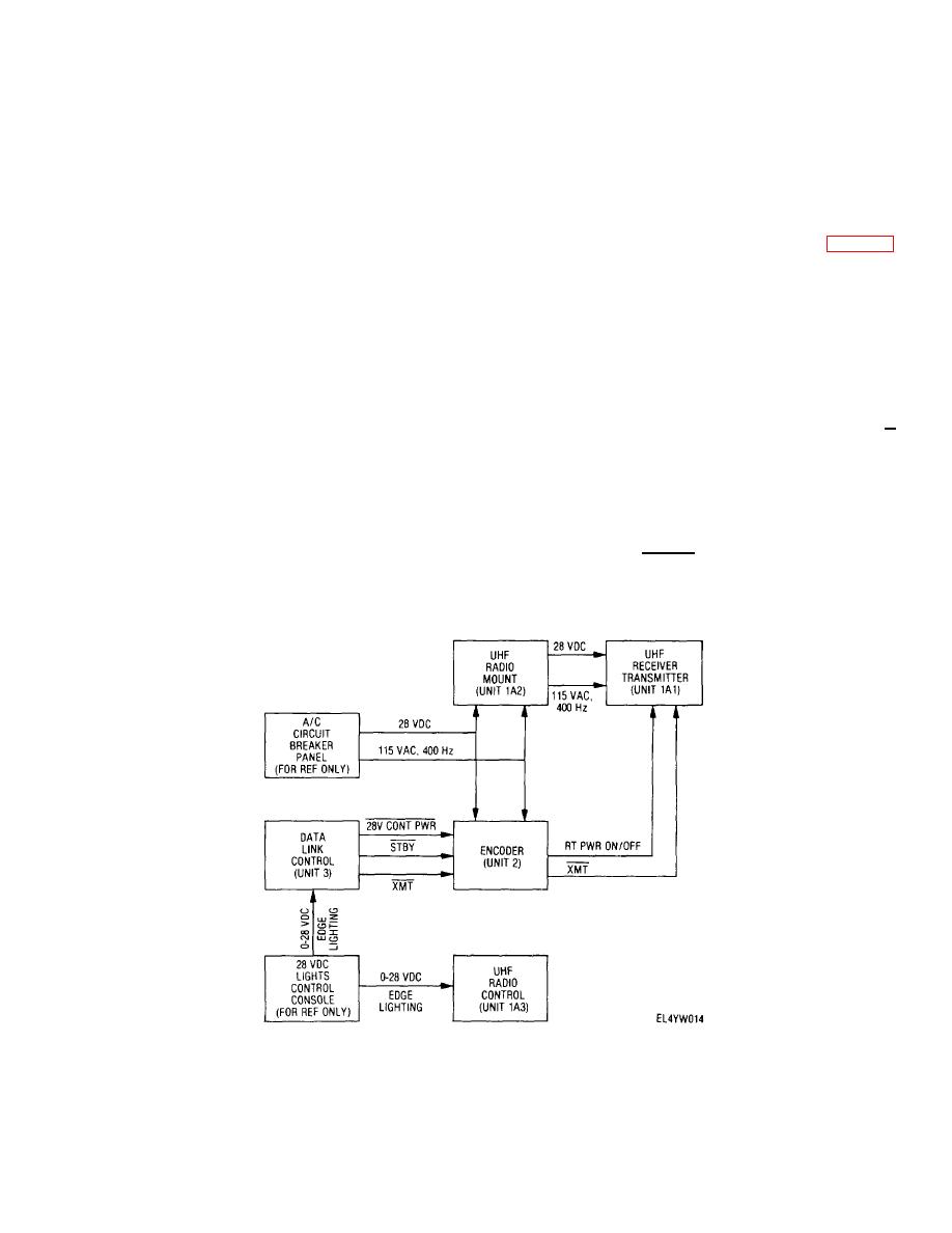
d. Power Distribution and Control (fig. 2-2)
lowing a synchronization or low rf power malfunction The
uhf radio control interfaces with the uhf receiver-
Primary power, consisting of 115 V ac, 400 Hz, single
transmitter to enable operator channel/frequency
phase and 28 V dc, is distributed directly to the encoder
selection.
and uhf radio mount The uhf radio mount, in turn,
c. BITE Operation BITE encompasses a
distributes the primary power to the uhf receiver-
network of self test circuits, some of which operate on a
transmitter. Adjustable dc power for edge lighting (0-28
continuous basis (on-line BITE), while others function
volts) is distributed to the data link control and uhf radio
only upon operator request (operator initiated BITE).
control from the aircraft dc lights control console
Continuous monitoring of power supply functions is
Application of 115 V ac primary power within the encoder
performed within the encoder, while synchronization and
is controlled by the data link control via the 28V CONT
low rf power are monitored continuously within the uhf
PWR line Power control of the uhf receiver-transmitter is
accomplished via the data link control STBY and XMT
receiver-transmitter In addition, during all data
output lines, which, in turn, control the RT PWR ON/OFF
transmitting periods, a demodulated sample of the
and XMT lines outputted by the encoder to the uhf
transmitted signal R/T FAULT is continuously monitored
receiver-transmitter In the transmit mode of operation,
by the encoder for proper data characteristics Two
the RT PWR ON/OFF and XMT signals transition low, in
modes of operator initiated BITE are provided airborne
which case the uhf receiver-transmitter is fully energized
and downlink.
During airborne BITE, a series of
and is capable of output transmission In the standby
functional tests are performed on the encoder using
mode of operation, XMT is high (22 8 V), in which case
simulated input data, while the resultant output data is
the uhf receiver-transmitter Is only partially energized
checked for proper data characteristics During downlink
and is incapable of transmission.
BITE, the encoder test sequence is repeated, followed by
continuous transmission of a fixed test pattern to the
Figure 2-2. System power distribution and control block diagram.
Change 1 2-2


 Previous Page
