TM 11-5841-287-30
synchronize data transfer from output memory to the
the end of the housekeeping sequence, the program
output format generator for realtime serial downlink
waits for the transfer of video data before resumption of
transmission During execution of the output program,
program sequencing Upon completion of the
data are transmitted in two-word groups Preamble/mode,
housekeeping sequence, branching is performed back to
ADAS, video A-field, and video B/C-field data are sent,
the main output program, at which time a new output
respectively Following each two-word transmission,
cycle Is started An additional program, coldstart, is
branching is performed to the hardware interrupt
provided for initializing various program and hardware
program, at which time further sequencing is dependent
controls following a microprocessor unit (MPU) reset at
on interrupt status If presence of a transmit register
equipment power-up
interrupt is detected, the next two words in sequence are
read from output memory for output formatting and
2-7.
Internal Clock Generator Section
transmission This cycle is repeated until transmission of
data is complete If a transmit register interrupt is not
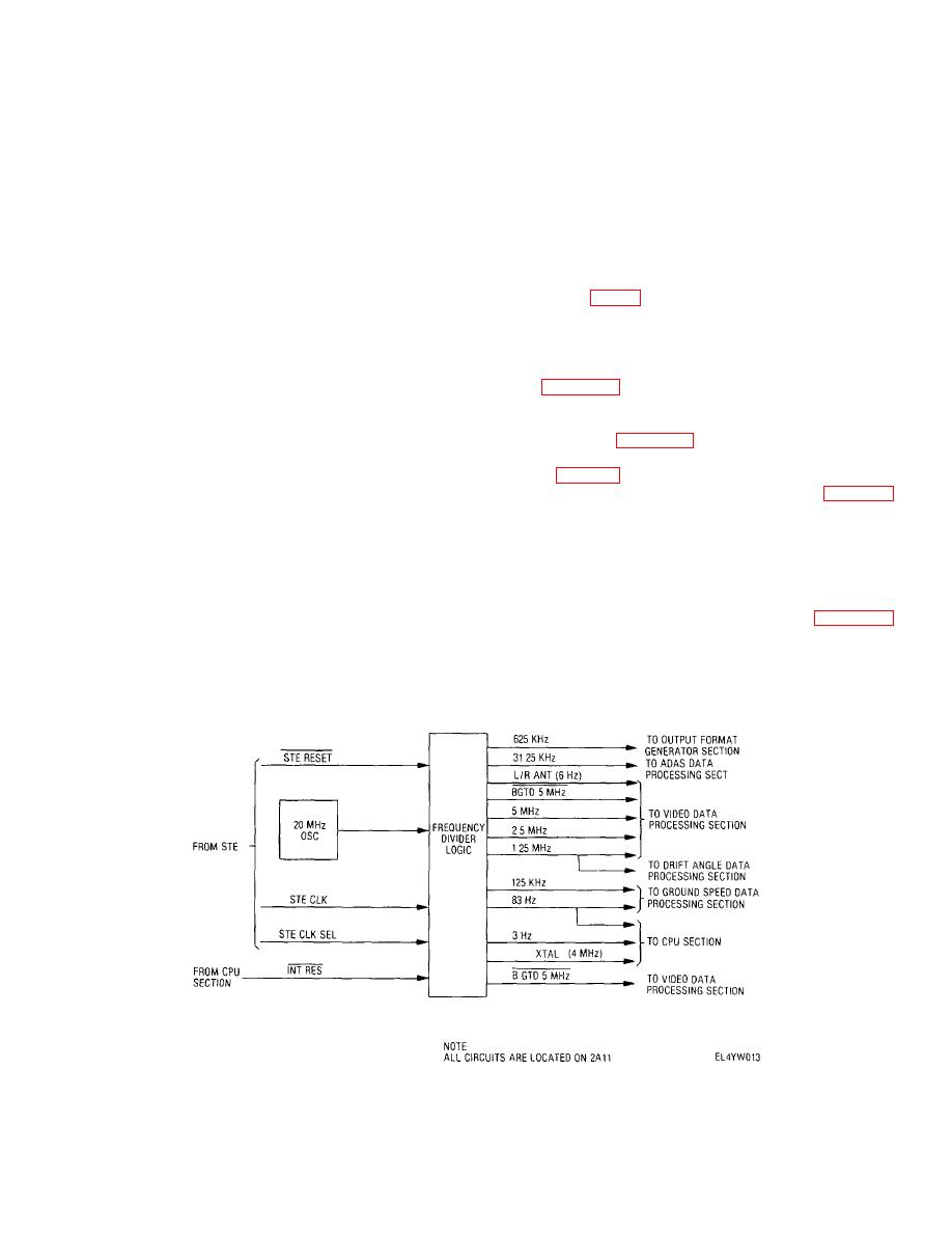
a. General The internal clock generator
detected at the start of the hardware interrupt program, a
provides a series of reference frequencies derived as
check for presence of ADAS input data is performed If
submultiples of a 20 MHz crystal-controlled reference
present, the ADAS data is processed into memory
oscillator The circuitry Is located on MPU/tlming module
Following execution of the ADAS sequences, drift angle
2A11 Figure 2-5 provides block diagram details
data processing sequences are executed If a self-test
b. Functional Description A 625 kHz signal is
(BITE) is in process during hardware interrupt program
supplied to the output format generator and receive
execution, program sequencing is modified to enable
register section (para 2-15) for data word counting and
monitoring of test data and display of test results
31 25 kHz is supplied to the ADAS data processing
Selection of self test and display of test status is provided
section (para 2-9) for ADAS clock simulation during BITE
by the data link control unit Return to the main output
operation The video data processing section (para 2-8)
program is accomplished at the end of the hardware
receives 5 MHz, 2 5 MHz and 1 25 MHz signals, which
interrupt sequence At the end of the main output
are utilized during video data transfer operations, a B
program, an alternating 1/0 bit pattern is transmitted until
GTD 5 MHz signal, which is used during BITE operation
the start of the next main output cycle
in place of the externally derived video accumulation
b. Housekeeping/Coldstart
Programs
clock (GTD CLK), and a 6 Hz signal (L/R), which is used
Parameters which are updated during housekeeping
during BITE operation for simulated antenna switching
include antenna mode, film speed, range/range delay,
The ground speed data processing section (para 2-10)
BITE request detection, ADAS input status, video B/C
receives a 125 kHz signal, which serves as a time base
field select, and drift angle acquisition The housekeeping
for unit counting, and an 83 Hz signal, which is used
program is executed primarily during the time between
during BITE operation in place of the normal ground
the end of the video data output transmission and
speed data signal
transfer of processed video data to output memory Near
Figure 2-5. Internal clock generator functional block diagram.
2-7


 Previous Page
