TM 11-5841-287-30
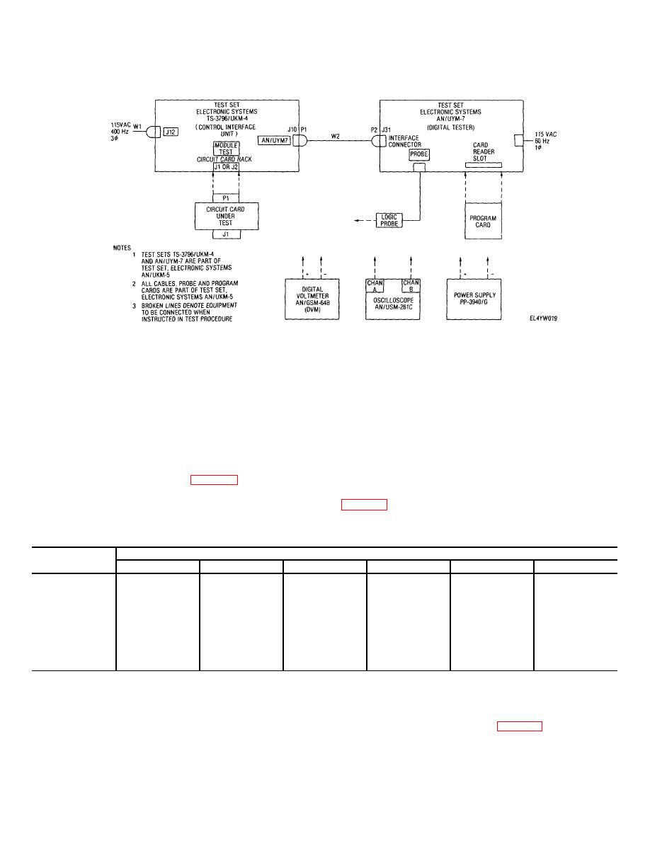
Figure 3-8. Typical test setup for circuit card testing
(11) Verify an indication of 4 O 0 01 V dc
NOTE
(12) Connect the positive lead of the digital
A logic "1" in the table will be Indicated
volt meter to pin 85 and negative lead to pin 86 on the
by the probe light illuminating. A logic
ex-tender card (This Is the monitor point for the output
"0" is indicated by the probe light being
voltage of the power supply.)
off. Dut to internal noise from the digital
(13) Adjust power supply output to voltage
tester, some levels may be intermittent
listed tester logic probe to each pin listed m table
Look for the most
headings in the first column of table 3-6 Then, connect
(14) Verify that all six logic levels are
digital on right side of table.
correct for common value such power supply setting in
Table 3-6. MT Channel lA/D Levels
Power supply
Output logic levels
settings(V)
J1-V
J1-20
J1-S
J1-17
J1-U
J1-18
0.28
0
0
0
0
0
0
0.88
0
0
1
0
0
1
1.43
0
1
0
0
1
0
2.00
0
1
1
0
1
1
2.57
1
0
0
1
0
0
3.14
1
0
1
1
0
1
3.71
1
1
0
1
1
0
4.30
1
1
1
1
1
1
(15)
Adjust power supply to 0 06 V dc Disconnect power supply and digital voltmeter
(16)
Connect the positive leads of the power supply and digital voltmeter to pm 3 on the extender card
(17)
Connect the negative leads of the power supply and digital voltmeter to pin 4 on the extender card
(18)
Repeat steps 13 and 14 while verifying that all ten logic levels are correct as per table 3-7
3-33


 Previous Page
