TM 11-6625-847-45
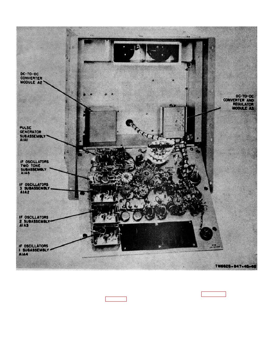
Figure 3-10. Test set A2, module and subassembly locations.
3-24.
Reassembly of Oscillator Subassemblies
A2A1A2, A2A1A3 and A2A1A4
proper position, as shown in figure 3-13, and install the
To reassemble an oscillator subassembly (fig. 3-13),
three crews (5) and six flat washers (6). Connect all
proceed as follows:
leads.
a. Secure the crystal socket clip (12) and the
c. Install the metallic standoff (4).
crystal unit (9) to the case (8), using the four washers
(11) and two nuts (10). Connect the leads.
3-13


 Previous Page
