TM 11-6625-847-45
3-27.
Reassembly of Dc-to-Dc Converter and
Regulator Module A3
To reassemble the dc-to-dc converter and regulator
module A3, proceed as given in a through f below.
washers (11) to secure the rectifier output filter
assembly (12) firmly in place.
b. Install the four screws (7) and eight washers (8)
to secure the input filter assembly (9) firmly in place.
c. Install the four screws (4) and eight washers (5)
to secure the regulator module (6) firmly in place.
d. Position the cover assembly (3), and press it
into place.
e. Place dc-to-dc converter and regulator module
A3 in its proper position on the bottom plate of test set
A2 (fig. 3-10). Align the four holes in the assembly base
with the four drilled holes in the bottom plate. Make
certain that assembly connector J1 (fig. 3-14) is plugged
in.
washers (2) to secure the dc-to-dc converter and
regulator module AS to the bottom plate.
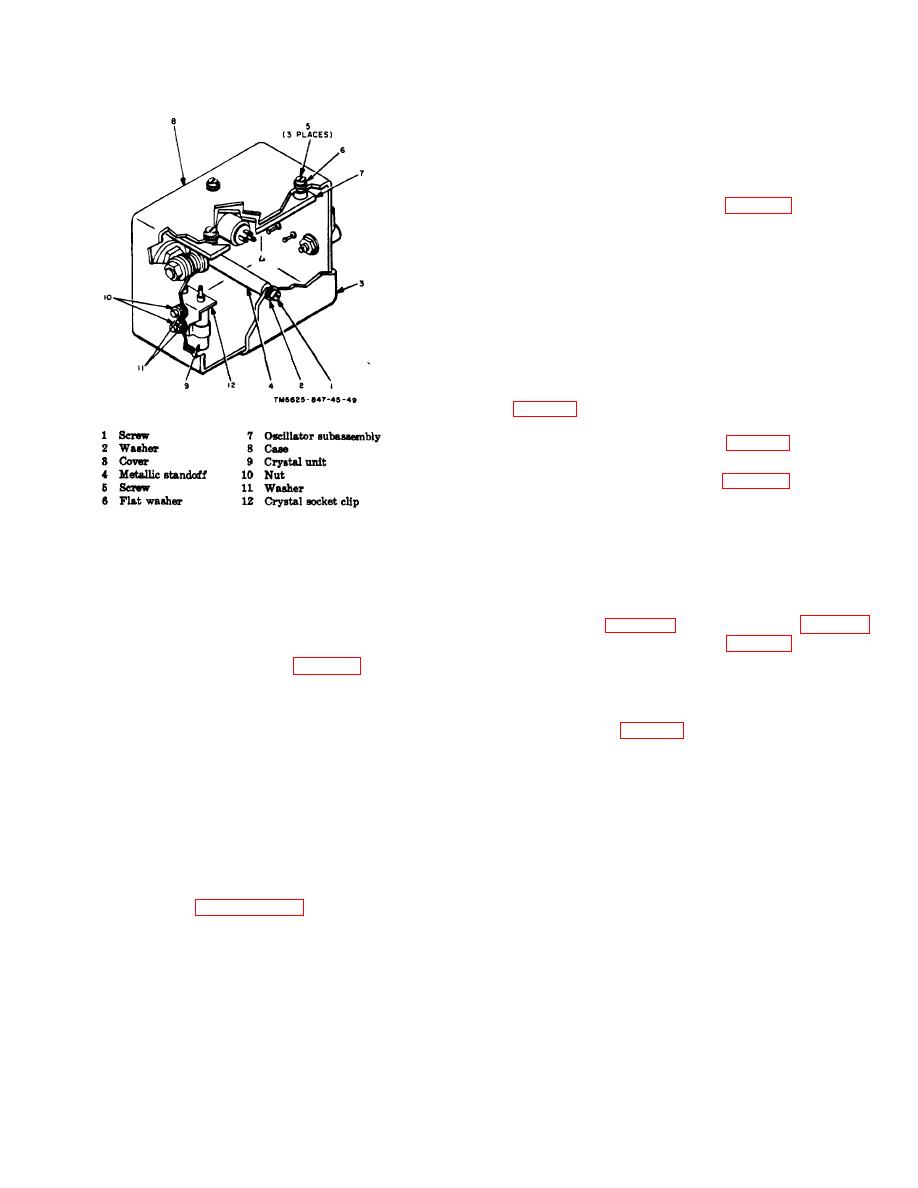
Figure 3-13. Oscillator subassembly.
3-28.
Removal of Sprocket Assembly Group A,
3-26.
Disassembly of Dc-to-Dc Converter and
Tray A1A1
Regulator Module A3
To remove either one of the two A-type sprocket
To disassemble the dc-to-dc converter and regulator
assembly groups (fig. 3-16) from tray A1A1 (figs. 3-17
module A3 after removal from the test set A2, proceed
and 3-1), remove the three nuts (1, fig. 3-16) and three
as given in a through d below.
cleats (2). Detach the chain from the sprocket (4) of the
sprocket assembly group being removed.
dc-to-dc converter and regulator module.
b. Remove the four screws (4) and eight washers
3-29.
Disassembly of Sprocket Assembly Group A,
(5) securing the regulator module (6). Remove the
Tray A1A1 (fig. 3-16)
regulator module.
c. Remove the four screws (7) and eight washers
To disassemble either one of the two A-type sprocket
(8) securing the input filter assembly (9). Remove the
assembly groups, proceed as given in a through g
input filter assembly.
below.
d. Remove the four screws (10) and eight washers
a. Remove the pin (3) from the sprocker (4), and
(11) securing the rectifier output filter assembly (12).
slide the sprocket off the assembly.
Remove the rectifier output filter assembly.
b. Remove the flat washer (5) and bearing holder
(6).
Note.
To remove parts, use
conventional
techniques Refer to paragraph 3-1.
3-16


 Previous Page
