TM 11-6625-847-45
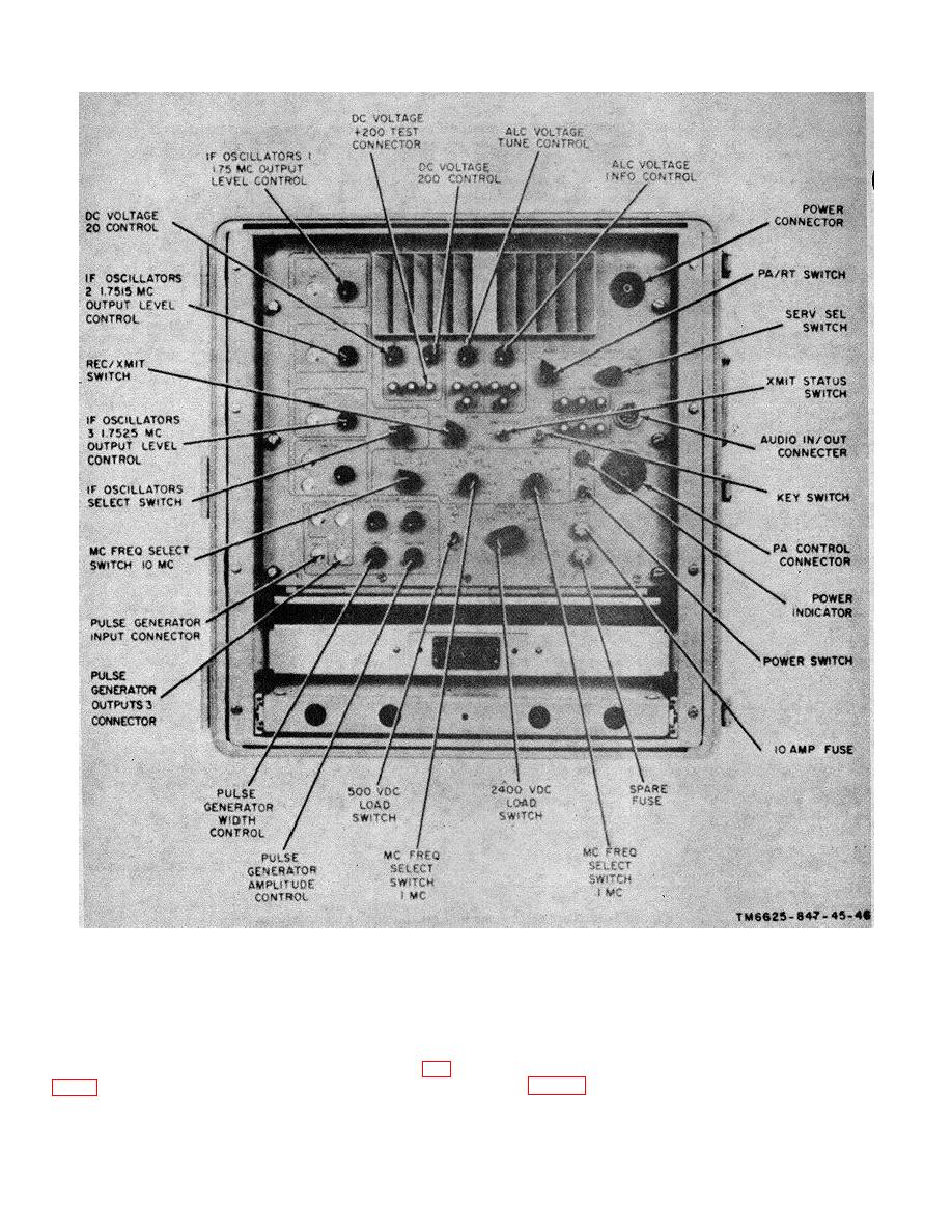
Figure 3-11. Test set A2, controls, switches, and connectors.
panel. Install the three front panel screws and two
d. Attach the cover (3) to the case, using the screw
washers which secure the oscillator subassembly to the
(1) and two washers (2).
front panel.
f. Connect the two leads to connector J2 and pin
position on the rear of the front plate of the test set (fig.
E1 (fig. 4-4).
Align the three holes in the oscillator
subassembly case with the matching holes in the front
3-14


 Previous Page
