TM 11-5841-287-30
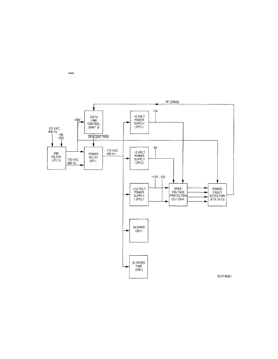
power relay K1 and to power fault detection logic located
potentiometer on each power supply permits nominal
on power fault detector module 2A13 In addition, +28 V
output voltage setting For encoder protection,
is supplied to the data link control for lamp power From
overvoltage sensors are located across each power
FL1, the 115 V ac is applied to contacts of relay K1 Relay
supply output Power supply functional status is
K1 is energized by placing the power switch on the data
monitored continuously In conjunction with operation of
link control in the STBY or XMT position, at which time
the power fault detection logic and ENCODER FAULT
the CONT PWR line goes low With relay K1 energized,
indicator on the data link control As long as the power
115 V ac is then applied to +5 volt power supply PS1, -5
supply voltages remain normal, the PF ERROR line is
volt power supply PS2, + 12 volt power supply PS3,
grounded causing the ENCODER FAULT indicator to
blower B1, and elapsed time meter M1 The power
remain off Should any power supply voltage drop below
supplies furnish regulated operating voltages for the
or rise above normal, the PF ERROR line is sent high by
encoder circuitry, and feature current limiting for overload
the power fault detection logic, illuminating the
protection
An
externally
accessible
ENCODER FAULT indicator
Figure 2-12. Encoding subsystem power supply and distribution block diagram.
2-19


 Previous Page
