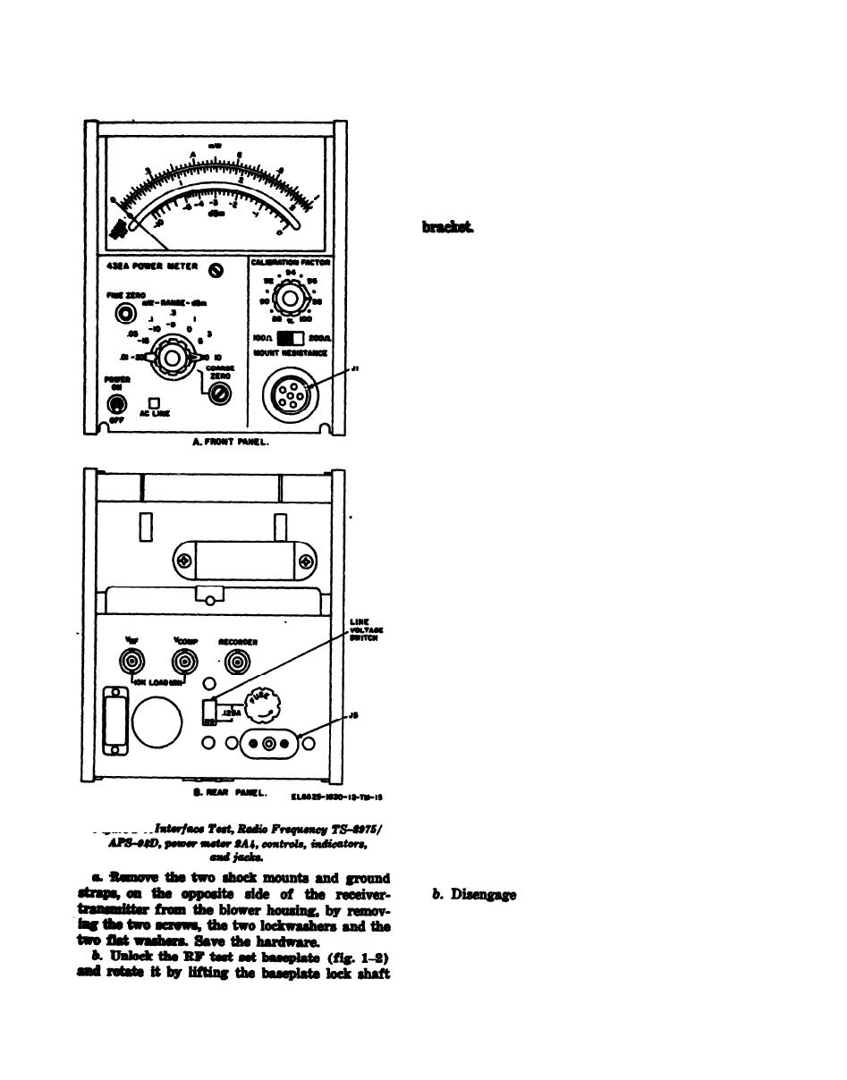
TM 11-6625-1830-12
so the receiver-transmitter may be mounted from
the rear of the rf test set. This makes the rt
mounting bracket more accessible.
a. With the receiver-transmitter blower hous-
ing in the up position and the antenna waveguide
ports to the left, position the receiver-transmitter
on the mounting bracket with the shock-
mount brackets resting against the rt mounting
d. Secure the receiver-transmitter to the RF
test set rt mounting bracket using the two screws,
the four flat washers and the two wing nuts sup
plied with the rf test set (23, fig. 1-4).
a Use the 1/2-inch hexagon socket wrench
and sliding bar handle (26 and 26, fig. 1-4),
applied with the RF test set, to loosen the 1/2-
inch self-locking hexagon nub at the detachable
and the nondetachable coupling of the clench-
ing rim clamp assembly until the detachable
coupling can be uncouple&
f. Remove the clenching rim clamp assembly
and housing aver. To prevent damage to the
cover, place it in a safe place.
g. Rotate the base plate of the rf test set un-
til the other clenching rim clamp assembly is
accessible and repeat the procedures given in e
and f above.
RT-899/APS-94D from Interface Test,
Radio Frequency TS-5975/APS-94D
(fig 2-12)
CAUTION
Make sure the RF test set power (fig.
2-6) and the control unit (fig. 2-5)
power is turned off, and the cables
connecting the control unit to the re-
ceiver-transmitter (fig. 29) are discon-
nected, before removing the receiver-
transmitter from the RF test set.
NOTE
Two men are required to remove the
receiver-transmitter from the RF test
set.
a. Remove the eight phillips head screws se-
- the flexible waveguide sections of sub-
assembly 2A1 to the antenna ports of the re-
ceiver-transmitter (c, fig. 2-12).
the switch clamp.
c. Hold 2A1 subassembly with one hand and
release the waveguide quick disconnect flanges
that secure waveguide section W16 to attenuator
2A1AT4. Carefully remove subassembly 2A1
front the RF test set.


 Previous Page
