TM 11-5840-281-35/1
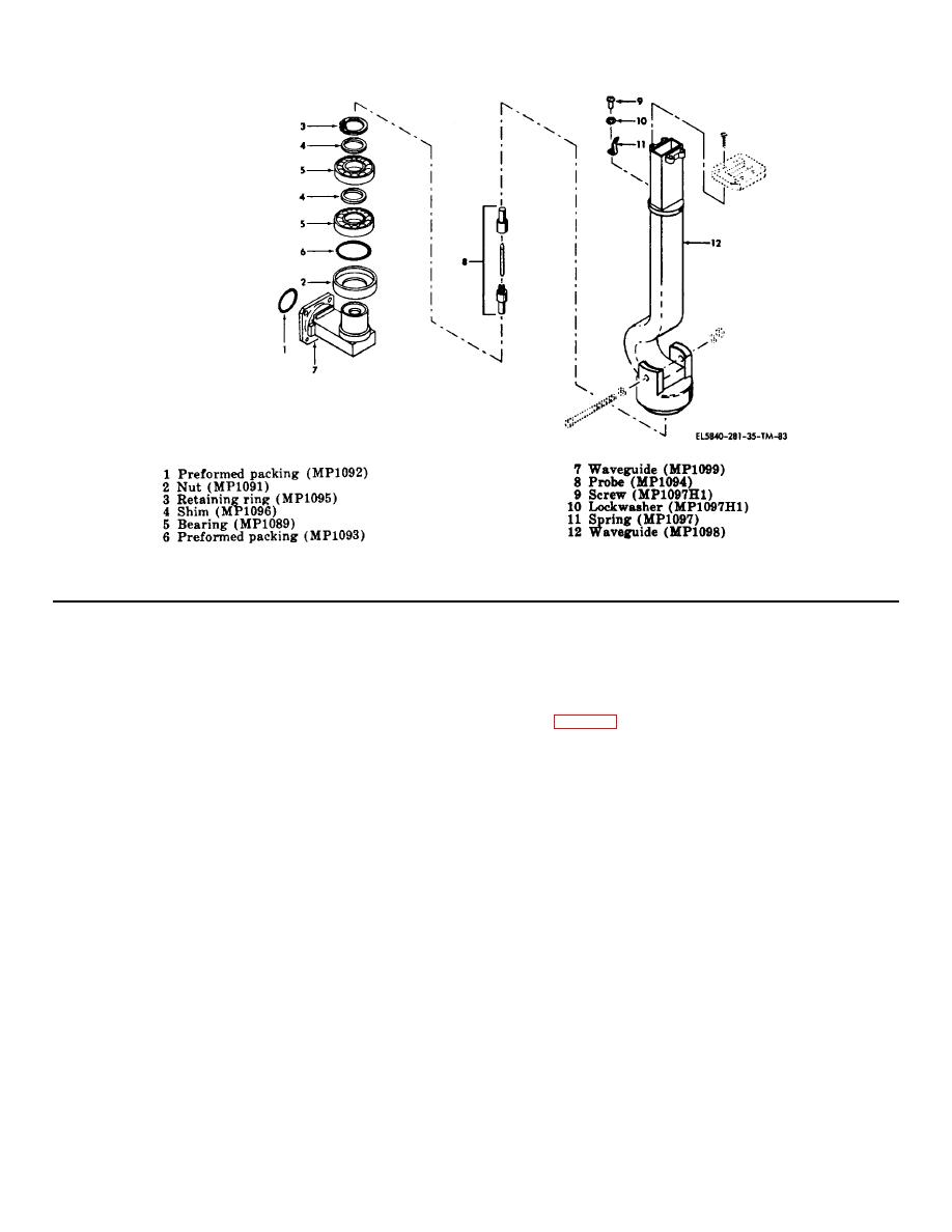
Figure 5-12. Azimuth rotary coupler, exploded view.
(4) Remove retaining ring (3) from wave- guide.
(6) Attach spring (11) to waveguide (12) using
(5) Remove shims (4), bearings (5), and preformed
screw (9) and lockwasher (10).
packing (6), from waveguide (7).
(6) Remove probe (8) from waveguide.
5-17. Disassembly and Assembly
of
Elevation
(7) Remove screw (9), lockwasher (10), and spring
Antenna Drive TG-114/TPN-8
(11), from waveguide (12).
b. Assembly. To assemble azimuth rotary coupler,
a. Disassembly. To disassemble Elevation An- tenna
proceed as follows:
Drive TG-114/TPN-8, proceed as follows:
(1) Lubricate bearings (5) with grease MI-G-23827.
(1) Remove four screws (1), lockwashers (2), flat
(2) Stack nut (2), preformed packing (6), bearings
washers (3) and support tube (4) from elevation drive
(5), and shims (4), on waveguide (7), and secure in place
housing (215).
with retaining ring (3).
(2) Remove two screws (5), lockwashers (6), flat
(3) Assemble probe (8) and install in waveguide
washers (7), and scope mount (8) from support tube (4).
(7).
(3) Remove two screws (9), lockwashers (10), flat
(4) Carefully insert assembled waveguide (7) into
washers (11), and angle bracket (12) from support tube
waveguide (12) making sure bearings (5) seat properly
(4).
in waveguide (12).
(4)
Remove cable assembly (13) connectors
(5) Secure waveguide (7) to waveguide (12) by
between J502 on elevation drive housing and J508 on
tightening nut (2).
10-35 actuator assembly.
NOTE
Shims (4) should be added or removed
to provide minimum end play without
binding.
5-40


 Previous Page
