TM 11-5841-287-12
beginning to verify the operational status of the
3-11. Organizational Troubleshooting Instructions
equipment
NOTE
instructions for the data transmitting set To use the table,
per- form the initial checks and adjustments (para 2-4)
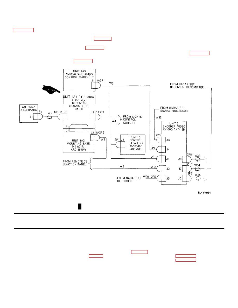
Although all interconnecting cables are
until an improper result or Indication is obtained Then,
supplied as part of the aircraft electronics
locate the appropriate malfunction in table 3-3 and
configuration, a data transmitting set
perform the associated tests and corrective actions
cabling diagram is provided in figure 3-2 as
When the malfunction has been corrected, repeat the
a troubleshooting aid.
initial checks and adjustments (para 2-4) from the
Figure 3-2. Data transmitting set cabling diagram.
Table 3-3. Organizational Troubleshooting
MALFUNCTION
TEST OR INSPECTION
CORRECTIVE ACTION
1.
ENCODER FAULT INDICATOR ON DATA LINK CONTROL ILLUMINATES IMMEDIATELY AFTER PLACING POWER SWITCH
IN STBY POSITION
Step 1. Check 115 VAC, 400 Hz fuses on encoder front panel.
Replace fuse(s) if defective.
Step 2. Check to see if encoder blower is operating.
If blower is not operating, replace encoder and data link control (para 3-12 b and c).
Step 3. Using multimeter, check cable W5 (fig 3-2) in accordance with applicable technical manual (Appendix A).
Replace cable W5 as necessary. If cable W5 is good, replace encoder and data link control (para 3-12 b and c).
2
RT FAULT INDICATOR ON DATA LINK CONTROL ILLUMINATES IMMEDIATELY AFTER PLACING POWER SWITCH IN STBY
POSITION
Step 1. Check fuses on uhf receiver-transmitter, uhf radio control and uhf radio mount.
Replace fuse(s) if defective.
Change 1 3-4


 Previous Page
