TM 11-5840-360-14-1-1
condition is not met, perform steps
22. Adjust Y-reference gain control R1 on Position
33 and 34.
Transmission PCB A2A8 to obtain exactly 10 volt peak-
to-peak signal.
33. Loosen CRT yoke clamp and carefully rotate the
23. Connect oscilloscope at pin P of EBL PCB
yoke until sweep origin moves vertically between
A2A9/extender card.
OFFSET switch settings. Tighten the yoke clamp,
24. Adjust X-reference gain control R7 on A2A8
insuring that the yoke does not slip down.
PCB to obtain exactly 10 volt peak-to-peak signal.
34. Repeat steps 28 through 32 above until
25. Observe the range rings, which should now be
requirements of steps 29, 31 and 32 are met
nearly circular but not necessarily centered.
simultaneously.
26. At A2A10 PCB, adjust R61 and R66 controls
35. Set OFFSET switch off. Set Indicator POWER
seven turns clockwise.
switch to OFF.
27. Observe that the octagonal sweep display has
36. Remove EBL PCB A9 and extender card. Insert
increased in size; verify that at least five range rings are
A9 PCB (without extender) into A9 slot of card basket
visible.
A2.
28. Adjust CURSOR control to position CRT
37. Remove Sweep Generator PCB A10 from card
mechanical cursor line at exactly 22.5 on relative
basket A2. Mount A10 PCB on extender card and insert
bearing scale.
extender card into A10 slot of card basket.
WARNING
38. Set Indicator POWER switch to ON.
115
VAC
IS
PRESENT
AT
39. Adjust R54 on the A2A10 PCB clockwise until
TERMINALS OF FL1 AND FL2 IN
the sweep just covers the face of the CRT, i.e., just until
VICINITY OF CRT TUBE SOCKET.
the straight sides of the octagon are not visible.
EXERCISE EXTREME CARE TO
40. Adjust R11 on the A2A10 PCB until the range
AVOID CONTACT.
rings are approximately centered on the vertical axis of
the display.
29. Locate the CRT centering magnet adjustment
41. Adjust R31 on the side of A2A10 PCB until the
tabs in the base of the yoke assembly. Carefully adjust
range rings are approximately centered on the
the tabs to position the displayed octagon with respect to
horizontal axis of the display.
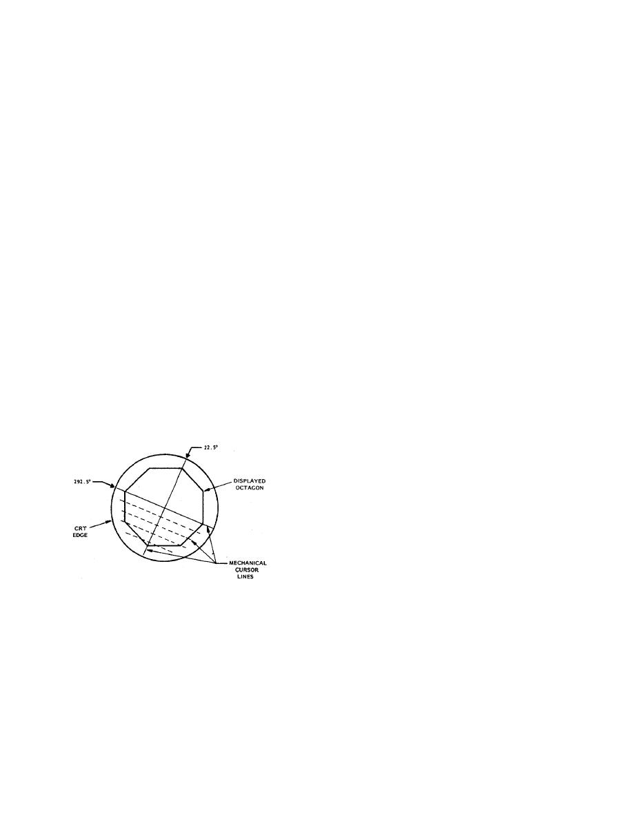
the mechanical cursor lines as shown below; insure that
42. Loosen captive screws and raise Indicator bezel
cursor lines intersect octagon internal angles at 22.5
assembly until it locks in position.
and 292.5
.
43. Connect multimeter, set to 5 Vdc scale, between
chassis (negative lead) and +E terminal of EBL
potentiometer R14 (on under side of bezel).
44. Adjust R70 on EBL PCB A2A9 to obtain exactly
+5.0 Vdc reading on multimeter.
45. Connect multimeter between chassis (positive
lead) and -E terminal of R14; verify multimeter reads -
5.0 0.1 Vdc.
46. Set Indicator POWER switch to OFF.
47. Remove A2A10 PCB and extender card. Insert
A10 PCB (without extender) into A10 slot of card basket
30. Adjust CURSOR control to position CRT
A2.
mechanical cursor line at exactly 0 on the relative
48. Mount EBL PCB A9 on extender card; insert
bearing scale. Adjust BRILLIANCE control to define
extender card into A9 slot of card basket A2.
point of sweep origin at center of CRT.
49. Set Indicator POWER switch to ON.
31. Adjust A1R12 and A2R12 on Sweep Output
50. With RANGE SELECT switch at 24 MILES,
assembly A3 to position the CRT sweep origin directly
adjust VRM handwheel to obtain 46600 yards (23 miles)
under the center of the mechanical cursor.
readout on VRM LED indicator at top of CRT. Adjust
32. While setting OFFSET switch alternately on and
VRM intensity control until VRM range ring is visible.
off, verify sweep origin moves vertically on CRT display,
51. Turn EBL front panel knob to position displayed
remaining under the mechanical cursor line for both
EBL at 0on relative bearing scale.
positions of the OFFSET switch.
52. Adjust R1 on Position Transmission PCB A2A8
NOTE:
to superimpose the EBL VRM dot on the VRM range
When the requirement of step 32 is
ring.
met, proceed to step 35. If that
5-62


 Previous Page
