TM 11-5841-287-30
Table 3-2. Encoder and Data Link Control Troubleshooting-Continued
MALFUNCTION
TEST OR INSPECTION
CORRECTIVE ACTION
Step4
Test 2A13 (para 3-34 in its entirety), 2A9 (para 3-31), and 2A5 (para 3-29) in order Perform steps 2 and 3 of Malfunction 7 without
repetition Replace defective circuit card (para 3-11)
Step 5
Test 2A16 (para 3-36), 2A13 (para 3-34a through 3-34c (8)) and 2All (para 3-32) m order Perform steps 2 and 3 of Malfunction 7 without
repetition Replace defective Circut card (para 3-11)
Step 6
Test 2A9 (para 3-31), 2A7 (para 3-30), 2A14 (para 3-35), and 2A13 (para 3-34a through 3-34c (8)) mn order Perform steps 2 and 3 of
Malfunction 7 without repetition Replace defective circuitcard
Step7
Set oscilloscope to 50microsecondsper division, normal triggered, on positve-going edges Monitor 2A13J1-15. Press AIRBORNE BITE
switch on data link control
(a)
The oscilloscope trace remains low throughout the BITE test(does not trigger) The logic level at pm 15 is low (LO)
(b)
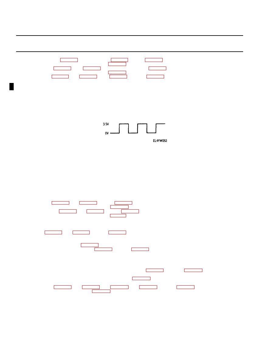
The oscilloscope triggers and remains high (3 5+ 1 5V) without interruption, the level at pm 15 is high (HI)
(c)
The oscilloscope trace may show a COMBINATION of HI and LO at pm 15
Refer to the following table to determine the next step. For pm 15, HI, LO, and COMBINATION are as defined above; for pms 18 and
Logiclevel
Step
Logic level
Step
at2A13J1pin
(below)
at2A13J1 pin:
(below)
18
P
15
18
P
15
HI
LO
LO
9
LO
HI
COMBINATION
15
HI
LO
HI
8
HI
HI
LO
18
HI
LO
COMBINATION
10
HI
HI
HI
19
LO
HI
LO
13
HI
HI
COMBINATION
20
Step 8 Test 2A3 (para 3-28), 2A9 (para 3-31), and 2A2 (para 3-27) in order Perform steps 2 and 3 of Malfunction 7 without repetition
Replace defective circuit card (para 3-11)
Step9
Test 2A4 (para 3-28), 2A9 (para 3-31), and 2A2 (para 3-27) in order Perform steps 2 and 3 of Malfunction 7 without repetition
Replace defective circuit card (para 3-1 1)
Step 10
Set oscilloscope for 0 2V per division and 50 microseconds per division Monitor (2A17JI-17 Place POWER switch on data limk
Replace defective circuit card ("ars 3-11)
(a) A pattern of pulses approximately 0 4 V in amplitude referenced to ground, each pulse approximately 13 microseconds wide, appears Test
2A9 (para 3-31), 2A7 (para 3-30), then 2A2 (para 3-27) Perform steps 2 and 3 of Malfunction 7 without repetition
(b) The pattern described in step 30(a) does not appear at any time Perform step 11
Step 11
Connect oscilloscope to 2A19XA17-26 Observe digital activity A pulse tram of normal logic levels (O 0 5 V low level and Replace
defective circuit d card (para 3-11) 3 51 5V high level with pulsewidths of approximately 13 microseconds should appear
(b) Correct pulses not present Test 2A7 (para 3-30), then 2A6 (para 3-29) Perform steps 2 and 3 of Malfunction 7 without repetition
(a) Correct pulse levels and widths are present, perform step 12.
Step 12
Check 2A19XA17-27 for a logic high level This signal cycles on and off during BITE You must restart by pressing DOWNLINK BITE
once to terminate BITE and once again after the green BlTE-IN-PRCS light goes out The high level should appear Replace defective
circuit card within 2 or 3 seconds after restarting the BIT test The level will then go low momentarily and return high again
(a) Signal is always low or does not reach a true high level Test 2A 16 (para 3-36), then 2A17 (para 3- 37) Perform steps 2 and 3 of
Malfunction 7
(b) Signal alternates high and low during BITE test Test 2A17 (para 3 -37) Perform steps 2 and 3 of Malfunction 7 without repetition Replace
defective circuit card
Step 13
Test 2A6 (para 3-29), 2A9 (para 3-31), 2A7 (para 3-30), 2A4 (para 3-28), then 2A2 (para 3-27) Perform steps 2 and 3 of Malfunction
Replace defective circuit card (para 3-11)
Change 1 3-9


 Previous Page
