TM 11-5841-287-30
data word onto the data bus The cycle is repeated un-til
b. Functional Description Aircraft ground
a total of 48 ADAS words are processed The various
speed is obtained directly from a film speed sensing
counting and control logic is started by signal RE-SET
circuit located in the radar set recorder Film speed, in
Signals VID BA and ADAS DISABLE are de rived from
turn, is a function of ground speed, range, and antenna
the control logic for application to the video data
mode The input signal (FILM SPEED) is received in the
processing section, where they are used to halt video
form of a variable pulse rate stream The higher the
data transfer during periods ADAS input data is
ground speed the faster the pulse rate, the higher rate
simultaneously being received
being 644 64 PPS at 300 knots/25 km/single antenna
c
ADAS BITE During BITE operation, the DO
The lowest rate of 40 29 PPS at 100 knots/100 km/both
antennas The measurement technique consists of
out-put of the input data latch transitions high, causing
counting a fixed rate clock between two successive FILM
simulated test data to be substituted m place of the
SPEED pulses Following initial amplification, FILM
normal system data Simulated ADAS data words are
SPEED is applied to the data selector, along with an 83
derived from BITE memory, while other BITE circuits
Hz BITE reference signal Operation of the data selector
provide the logic necessary for simulation of the ADAS
is controlled by the DO output of the input data latch,
R/W control signal ADAS clock simulation is provided by
which is clocked low during normal operation in
a 31 2 kHz BITE clock derived from the internal clock
conjunction with signals 0002 and WC While DO is low,
generator A + 5 volt level is substituted for the MODE
the FILM SPEED signal is applied to the grated counter
signal to simulate BCD format
and control logic The gated counter is enabled under
program control by data signal D5 When D5 goes high,
2-10. Ground Speed Input Data Processing Section
the control logic is G1iabled and the counter is gated on
by the next high-to-low transition of FILM SPEED The
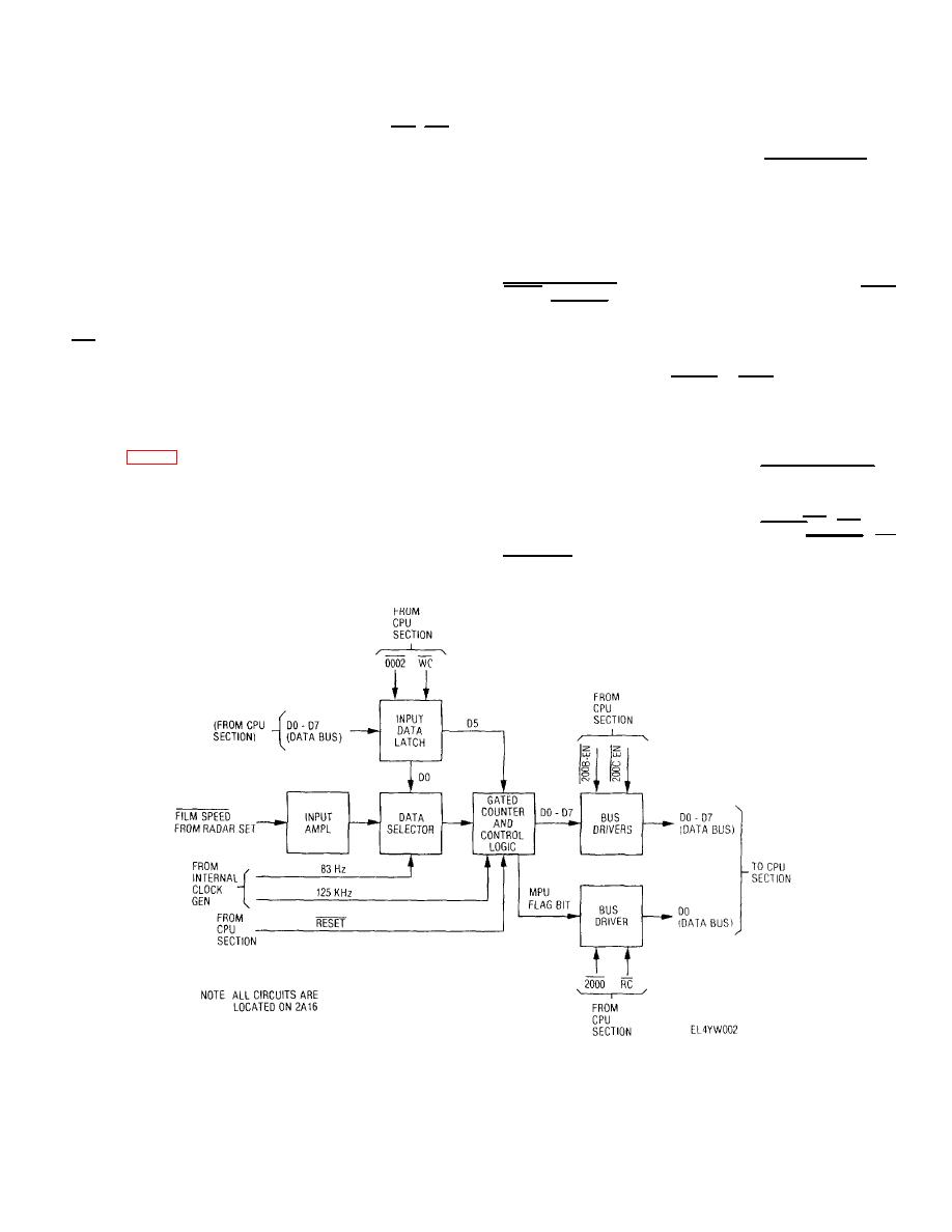
a. General The function of the ground speed
counter is gated off by the second high-to-low transition
input data processing circuitry is to convert ground speed
and a flag bit is generated When the flag bit is read by
input signals received from the radar set to 8-bit parallel
the CPU in conjunction with signals 2000 and RC, ihe
format for transfer to the output memory section The
counter's output is then read using signals 200B-EN and
circuitry, located on ADAS control module A16, consists
200C-EN The counter output is two 8-bit words whose
functionally of an input ampflifier and data latch, data
combined value corresponds to the number of 125 kHz
selector, gated counter and control logic, and bus
cycles counted between the two consecutive
drivers.
Figure 2-7. Ground speed data processing functional block diagram.
2-11


 Previous Page
